
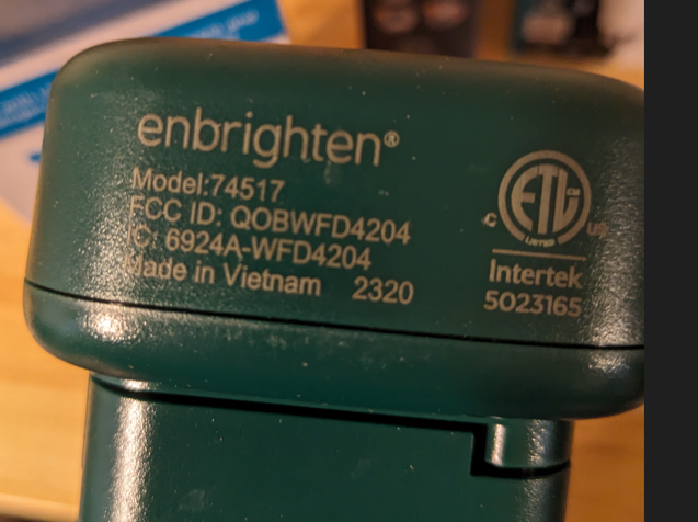
Device Info
- Model # 74517 - WDF4204
- FCC ID: QOBWFD4204
Acquisition
- Got this 6 outlet smart outdoor yard stake from the local return auction for $2.50. Normally these go for $10-20.

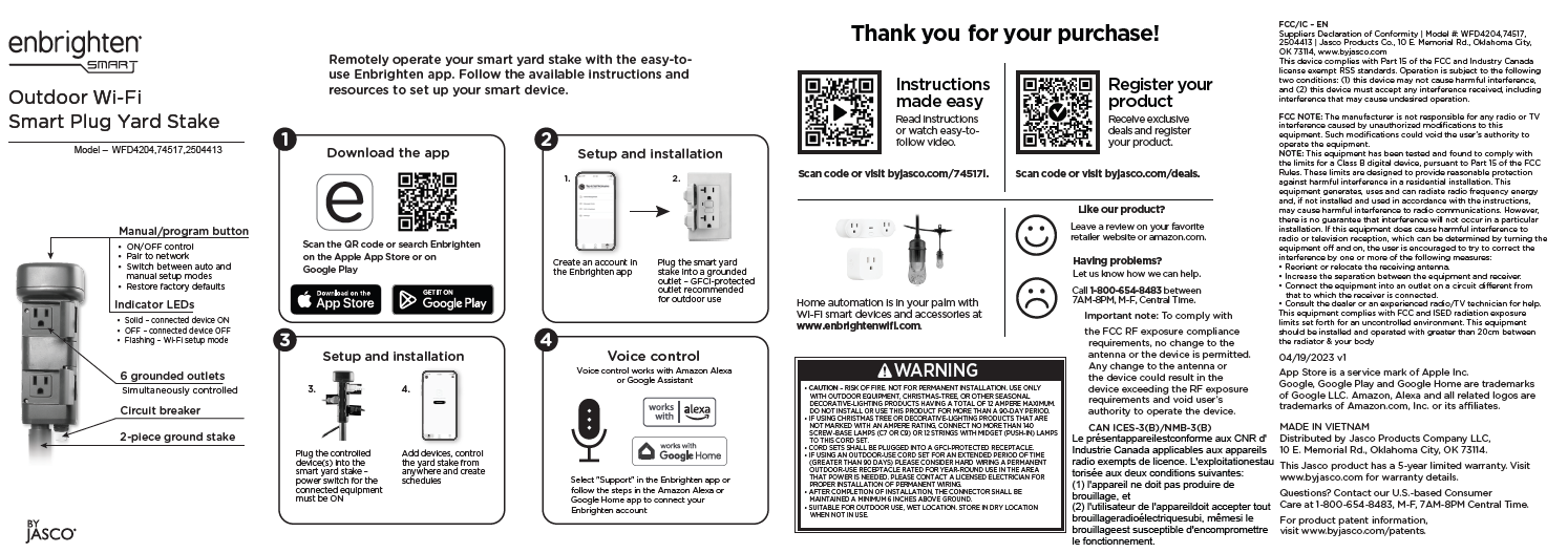
FCC ID Lookup
- Look up the model number online to get an idea of what to expect inside

CB2S Module
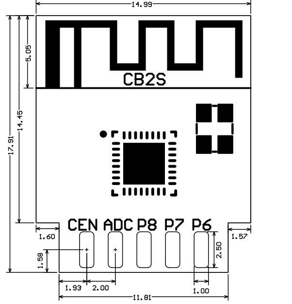
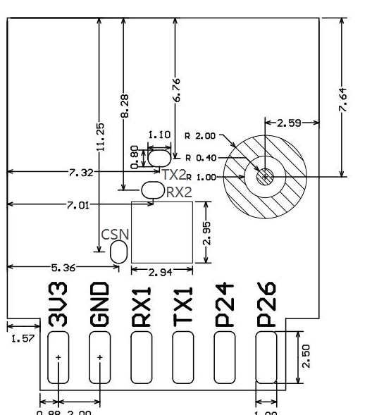
- Pin diagram available online
- https://developer.tuya.com/en/docs/iot/cb2s-module-datasheet?id=Kafgfsa2aaypq
| Pin number | Symbol | I/O type | Function | |
|---|---|---|---|---|
| 1 | 3V3 | P | Power supply 3V3 | |
| 2 | P6 | I/O | Support hardware PWM and correspond to P6 of the IC | |
| 3 | GND | P | Power supply reference ground | |
| 4 | P7 | I/O | Support hardware PWM and correspond to P7 of the IC | |
| 5 | RX1 | I/O | UART_RX1, which is used for receiving user data and corresponds to P10 of the IC. Do not pull it up. By default, the MCU serial port should be in low-level or high-impedance state. | |
| 6 | P8 | I/O | Support hardware PWM and correspond to P8 of the IC | |
| 7 | TX1 | I/O | UART_TX1, which is used for transmitting user data and corresponds to P11 of the IC. Do not pull it up. By default, the MCU serial port should be in low-level or high-impedance state. | |
| 8 | ADC | I/O | ADC, which corresponds to P23 of the IC | |
| 9 | P24 | I/O | Support hardware PWM and correspond to P24 of the IC | |
| 10 | CEN | I/O | Reset pin | |
| 11 | P26 | I/O | Support hardware PWM and correspond to P26 of the IC | |
| Test point | RX2 | I/O | UART_RX2, which corresponds to P1 of the IC. This pin is not allowed to use. | |
| Test point | TX2 | I/O | UART_TX2, which is used for outputting logs and corresponds to P0 of the IC | |
| Test point | CSN | I/O | Mode selection pin. If it is connected to the ground before being powered on, enter the firmware test mode. If it is not connected or connected to VCC before being powered on, enter the firmware application mode. It corresponds to P21 of the IC. |
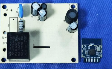
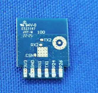
- Drawing of the front and back of module
Wireless Exploits
- There has been alot of great work on exploiting these IOT devices that are associated with the TUYA system of systems. The Tuya-Cloudcutter software has been updated and figured I’d give this another shot. I had tried to use this a year or so back without luck, maybe this device will be different…
Tuya-Cloudcutter
- https://github.com/tuya-cloudcutter/tuya-cloudcutter
- https://rb9.nl/posts/2022-03-29-light-jailbreaking-exploiting-tuya-iot-devices/
DigiblurDIY Guide
- I followed DigiblurDIY’s guide to setup a Raspberry Pi 4 (8GB RAM) to work the exploit.
- After setting all this up… turns out the device when plugged in would not even power on…. had to crack it open anyways to look at the hardware.
Teardown & Connections
External Photos
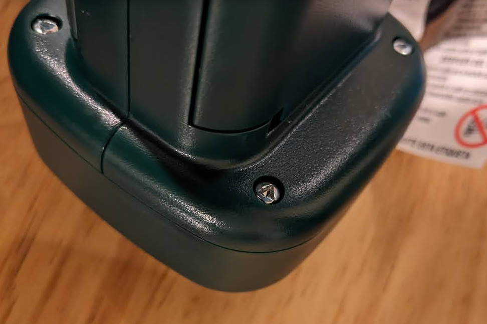
- Gotta love triangle security screws… four of them and the top can come off
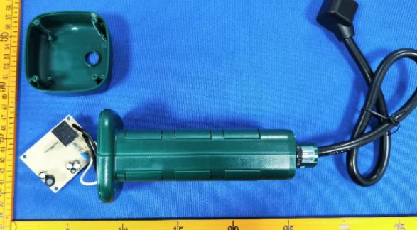
Internal Photos
- looks just like the internal photos from FCC database
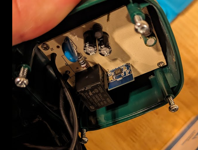
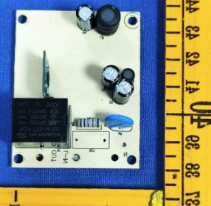
- Better look at the CB2S module and the single relay for the 6 outlets
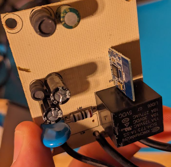
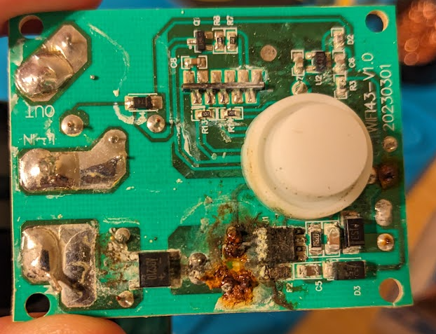
- Welp…. that might be the issue with it not powering on…
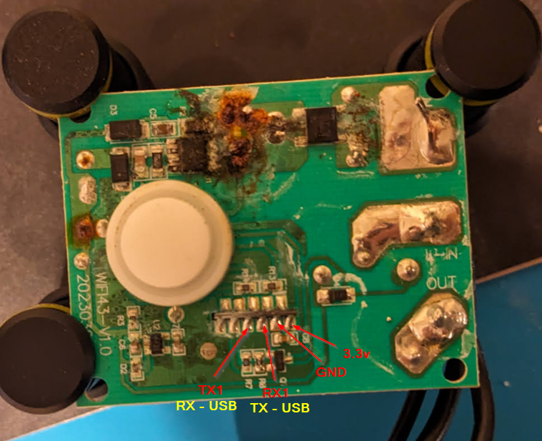
- Putting it on the pcb holder and mapping out the pins for the serial to usb connection
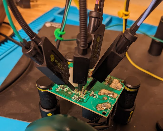
- All wired up and connected to the computer
Firmware Dump
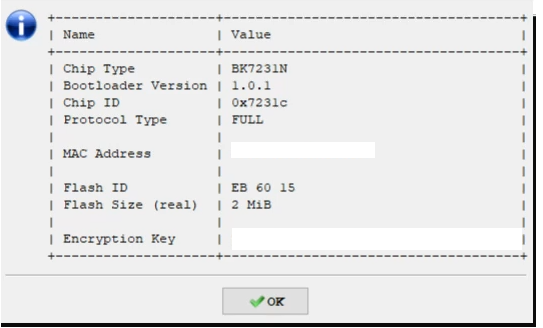
- Serial to USB converter connected up to computer and ltchiptool was used to interact with the CB2S module.
- https://github.com/libretiny-eu/ltchiptool
Chip Info
Read Flash
- Firmware saved twice
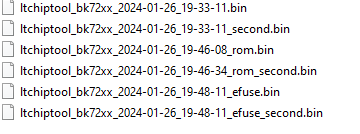
- Reading the firmware with LTChiptool to get pin assignments and configurations
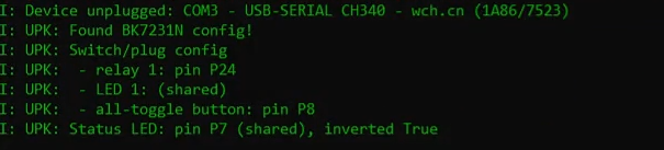
ESPHome
ESPHome Config
1
2
3
4
5
6
7
8
9
10
11
12
13
14
15
16
17
18
19
20
21
22
23
24
25
26
27
28
29
30
31
32
33
34
35
36
37
esphome:
  name: enbrighten_WFD4204_1
bk72xx:
  board: generic-bk7231n-qfn32-tuya
logger:
web_server:
captive_portal:
mdns:
api:
ota:
wifi:
  ssid: !secret wifi_ssid2
  password: !secret wifi_password2
  ap:
text_sensor:
  - platform: libretiny
    version:
      name: LibreTiny Version
binary_sensor:
  - platform: gpio
    id: binary_switch_1
    pin:
      number: P8
      inverted: true
      mode: INPUT_PULLUP
    on_press:
      then:
        - switch.toggle: switch_1
switch:
  - platform: gpio
    id: switch_1
    name: Relay 1
    pin: P24
status_led:
  pin:
    number: P7
    inverted: true
- In Home Assistant and ESPHome, a new device is created matching the device name in the YAML. Device can be installed, downloaded and flashed using LTChiptool.
ESPHome Operation
- After Flashing and power cycling…. device would not integrate with Home Assistant. Router would see the IP address pop up but when attempting to add device into Home Assistant it would not establish a connection.
- Disconnecting the PCB from the holder and plugging in to 120v the device would not power on. Clearly the damage PCB was not completing the circuit to power on the device.
Final Thoughts
- Was able to read and write to the CB2S module but think the power issues and overall damage to the PCB are going to limit the usefulness of the device.
- Bright side is if I need a CB2S module for another project this is readily available. Not going to be upset over a $2.50 returned item.