
- I picked up this dual outdoor smart switch at the local return auction this week. When I see items like this I typically just bid the minimum and if I win…great.
Device Info
- I start with looking the device up online and trying to figure out what to expect when I open it up.
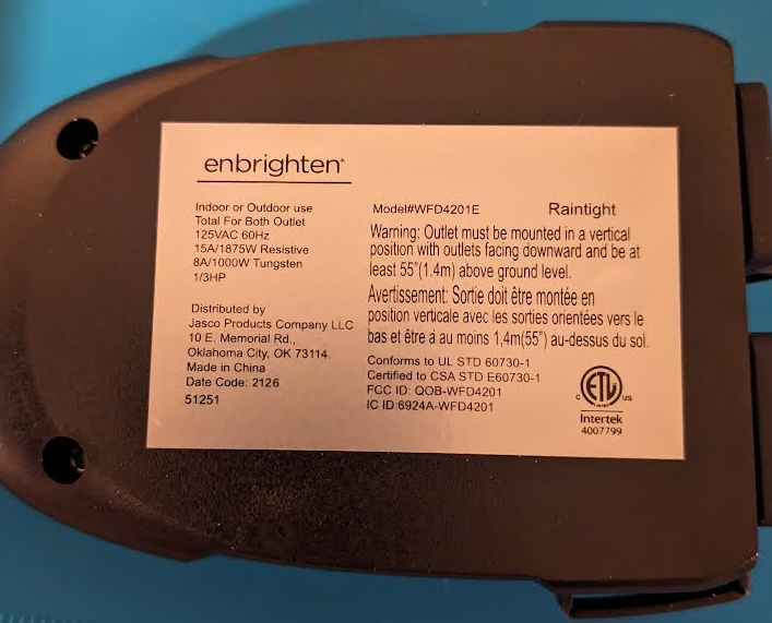
- Model: WFD4201E
- FCC ID: QOB-WFD4201
- https://fcc.report/FCC-ID/QOB-WFD4201/
 * https://fcc.report/FCC-ID/QOB-WFD4201/4852019
- No Internal Photos
- Really not that much information for this specific model in the FCC database.
Acquisition
- Won the auction for this device for only $2.50. Think these are typical in the $10-20 range.

Teardown & Connections
External Photos
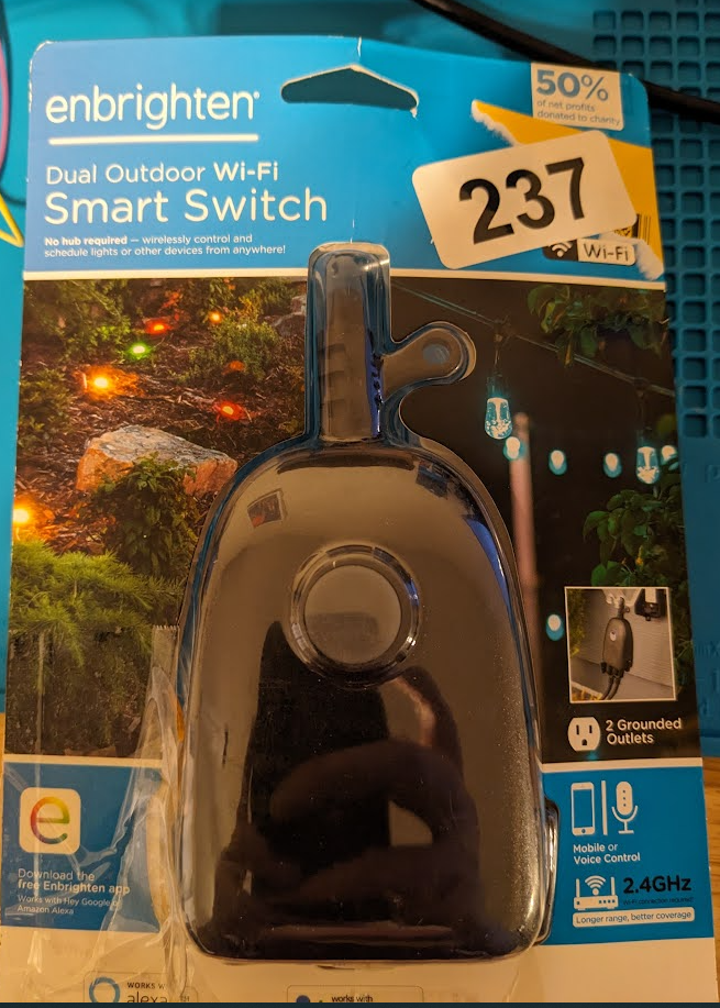
- Product packaging. Looks like it was opened and returned.
![a1a4fa418b738ce88d917fd300e733f4.png]()
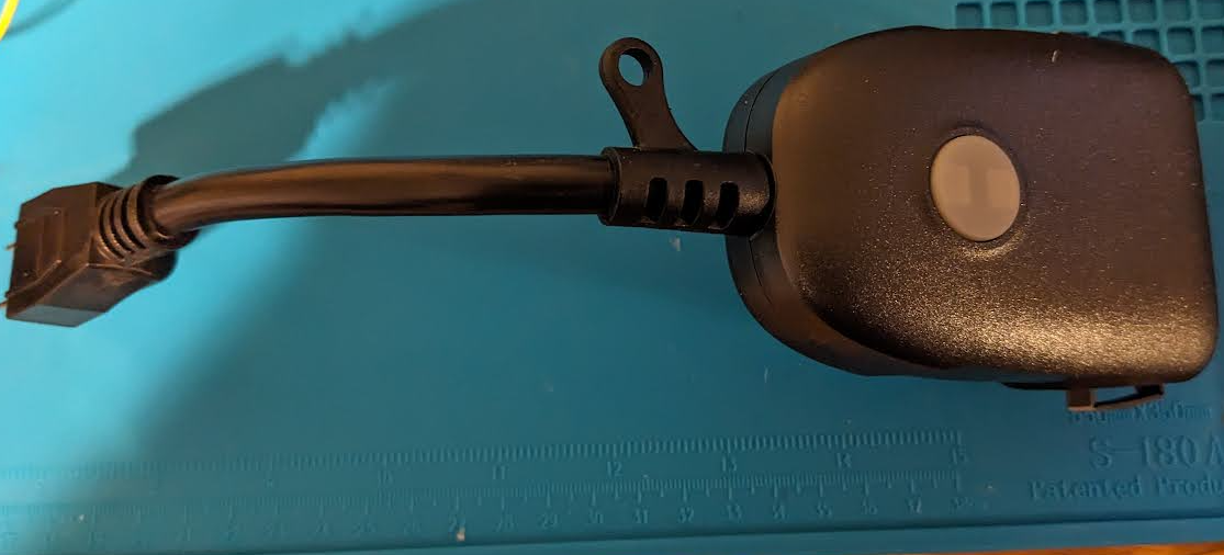
- Taking it out of the packaging, top view
![5f84245f4334ff777ece6992f8d3e6f4.png]()
- Bottom view with device information
![9e6cbba1cad637490df4802762b60ddd.png]()
Internal Photos
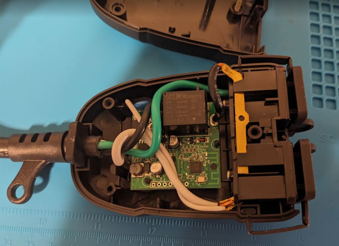
- There are 3 screws holding the case together. Two exposed and one hidden under the sticker.
![49252ae7d9208e0e5af28042a9d245da.png]()
- Top of PCB has pin headers [3v, IO0, TX, RX, GND]
- These did not function when attempting to read and write to the chip. The backside of the PCB had additional pads that worked correctly when trying to interact.
![6a4af14229f2903c2fde2918570dc9e3.png]()
- These did not function when attempting to read and write to the chip. The backside of the PCB had additional pads that worked correctly when trying to interact.
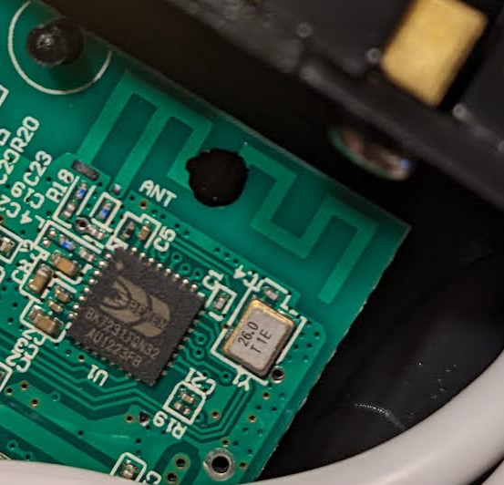
- Zooming in on the chip and it’s a BK7231TQN32
![65031031c78c0c06518b329bf892b7a0.png]()
![3b21d32d7f6563b4467f24ba29dc84ff.png]()
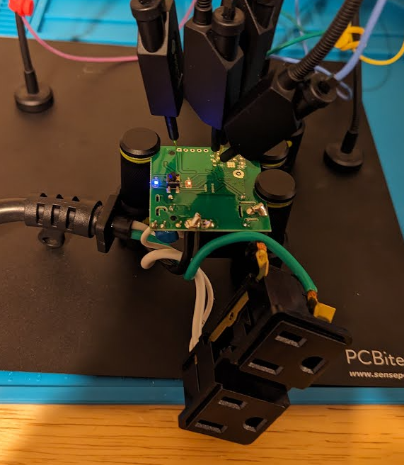
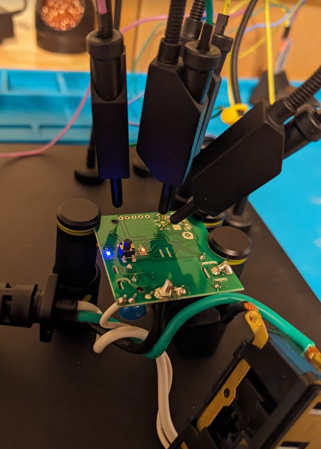
- Backside of the PCB with pads connected for GND, TX, RX. The 3.3v Pad was used from the 5 pin row header visible from the front/back.
Firmware Dump
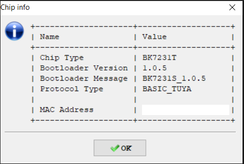
- Serial to USB converter connected up to computer and ltchiptool was used to interact with the BK7231T chip.
- Chip info showing in fact a BK7231T chip and basic tuya protocol.
![7b69728e6b35686994b4724b08e67f1a.png]()
Read Flash
- I typically save the firmware twice just in case something glitched. Compare the two to make sure they are same size, etc.
![4838abb63581e6ddf6652d59889ff5cc.png]()
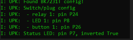
- With the firmware saved, LTchiptool can read it back to view the TUYA pin assignments and configuration.
![b025ebc9cf332336175a5f9cd01f7a8e.png]()

ESPHome
ESPHome config
- Again using LTChiptool the pin config information is used to generate a ESPHome YAML config file for the device. Add in additional WIFI options and remove unwanted extras from the stock YAML generated file. Final result for integration is below.
1
2
3
4
5
6
7
8
9
10
11
12
13
14
15
16
17
18
19
20
21
22
23
24
25
26
27
28
29
30
31
32
33
34
35
36
37
38
39
40
41
42
43
44
45
46
47
48
49
50
51
52
53
54
55
56
esphome:
  name: enbrighten-dual-2
  friendly_name: enbrighten-dual-2
bk72xx:
  board: generic-bk7231t-qfn32-tuya
logger:
web_server:
captive_portal:
mdns:
api:
ota:
wifi:
  ssid: !secret wifi_ssid2
  password: !secret wifi_password2
  fast_connect: true
  manual_ip:
    static_ip: 192.168.XX.XX
    gateway: 192.168.X0.1
    subnet: 255.255.255.0
text_sensor:
  - platform: libretiny
    version:
      name: LibreTiny Version
output:
  - platform: libretiny_pwm
    id: output_led_1
    pin:
      number: P8
      inverted: true
light:
  - platform: monochromatic
    id: light_switch_1
    output: output_led_1
binary_sensor:
  - platform: gpio
    id: binary_switch_1
    pin:
      number: P26
      inverted: true
      mode: INPUT_PULLUP
    on_press:
      then:
        - switch.toggle: switch_1
switch:
  - platform: gpio
    id: switch_1
    name: Relay 1
    pin: P24
    on_turn_on:
      - light.turn_on: light_switch_1
    on_turn_off:
      - light.turn_off: light_switch_1
status_led:
  pin:
    number: P7
    inverted: true
- In Home Assistant and ESPHome, a new device is created matching the device name in the YAML. Device can be installed, downloaded and flashed using LTChiptool.
ESPHome Operation
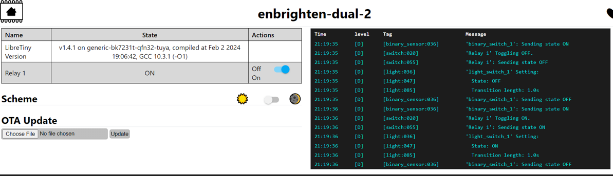
- After flashing and power cycling the device. Pins were unhooked and the 120V outlet is plugged in. After a few seconds the device joined
- Operation through home assistant app and webserver on chip successfully turns the single relay on and off
![6da27b5dbee1e0abb89f5bfa23720f0d.png]()
Final Thoughts
- The device has two 120v outlets but only one relay turning them on and off. Nice thing about this is in addition to the config created above, the BK7321T also supports BLE which could enable this device to act as a relay. Since this is an outdoor device it could capture BLE traffic for sensors outside in the backyard or garden and relay them up to homeassistant over the WIFI.