
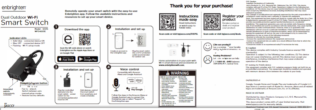
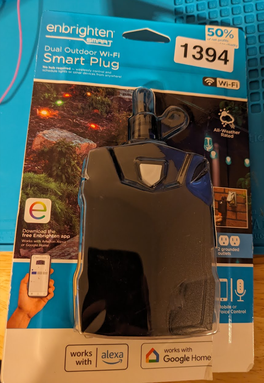
- Dual outdoor smart switch by Enbrighten picked up at the local auction return this week.
Device Info
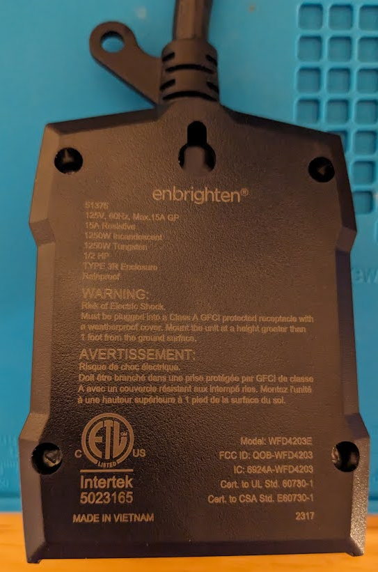
- Model: WFD4203E
- FCC ID: QOB-WFD4203
Acquisition
- Another cheap win at only $3. These go for $10-20 new.

FCC lookup
- Loking up the FCC ID online
- https://fcc.report/FCC-ID/QOB-WFD4203
- User manual available
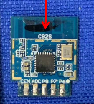
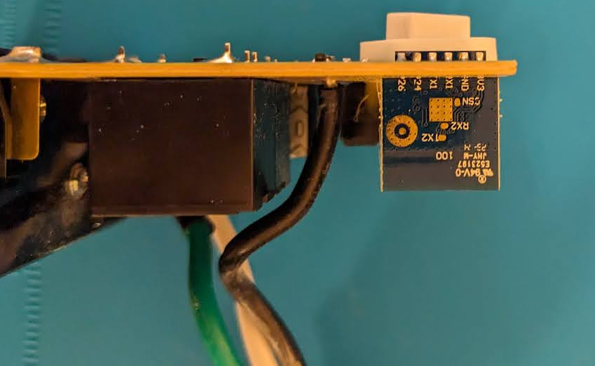
- Internal photos in the database show a CB2S module attached to the main PCB.
CB2S Module
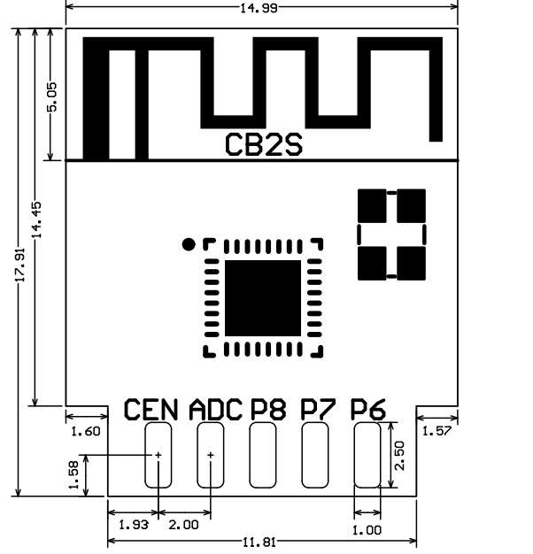
- Pin diagram available online
- https://developer.tuya.com/en/docs/iot/cb2s-module-datasheet?id=Kafgfsa2aaypq
| Pin number | Symbol | I/O type | Function | |
|---|---|---|---|---|
| 1 | 3V3 | P | Power supply 3V3 | |
| 2 | P6 | I/O | Support hardware PWM and correspond to P6 of the IC | |
| 3 | GND | P | Power supply reference ground | |
| 4 | P7 | I/O | Support hardware PWM and correspond to P7 of the IC | |
| 5 | RX1 | I/O | UART_RX1, which is used for receiving user data and corresponds to P10 of the IC. Do not pull it up. By default, the MCU serial port should be in low-level or high-impedance state. | |
| 6 | P8 | I/O | Support hardware PWM and correspond to P8 of the IC | |
| 7 | TX1 | I/O | UART_TX1, which is used for transmitting user data and corresponds to P11 of the IC. Do not pull it up. By default, the MCU serial port should be in low-level or high-impedance state. | |
| 8 | ADC | I/O | ADC, which corresponds to P23 of the IC | |
| 9 | P24 | I/O | Support hardware PWM and correspond to P24 of the IC | |
| 10 | CEN | I/O | Reset pin | |
| 11 | P26 | I/O | Support hardware PWM and correspond to P26 of the IC | |
| Test point | RX2 | I/O | UART_RX2, which corresponds to P1 of the IC. This pin is not allowed to use. | |
| Test point | TX2 | I/O | UART_TX2, which is used for outputting logs and corresponds to P0 of the IC | |
| Test point | CSN | I/O | Mode selection pin. If it is connected to the ground before being powered on, enter the firmware test mode. If it is not connected or connected to VCC before being powered on, enter the firmware application mode. It corresponds to P21 of the IC. |
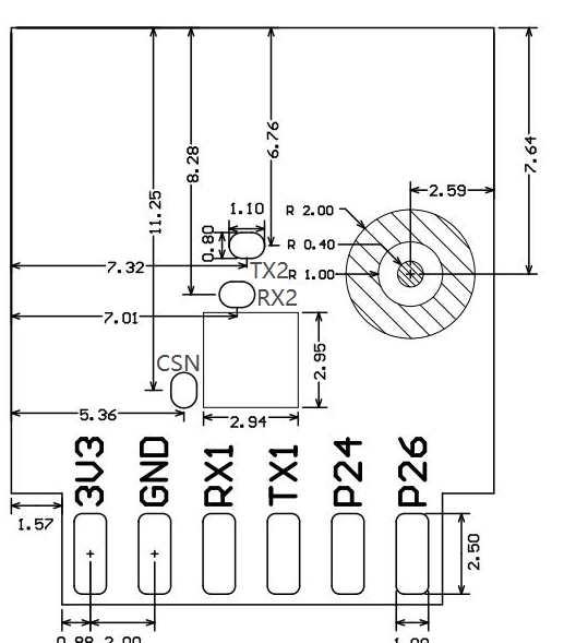
- Drawing of the front and back of module
Teardown & Connections
External Photos
- Packaging opened and returned.
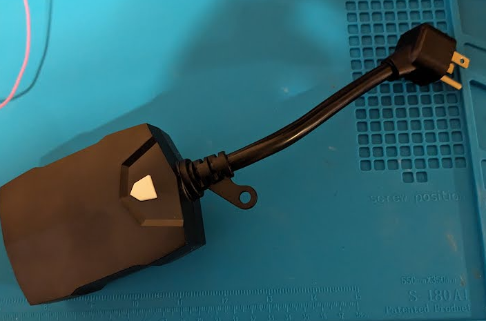
- Top of device
- Bottom of device with label
Internal Photos
- There are four triangle screws holding the back cover on. Once open, the PCB with two relays and the CB2S module are exposed.
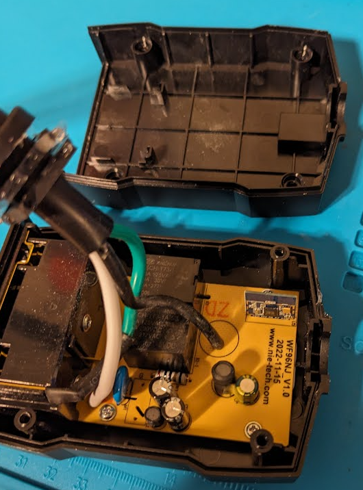
- Orientation of the CB2S module shows 3.3v location towards the top and outside of the PCB.
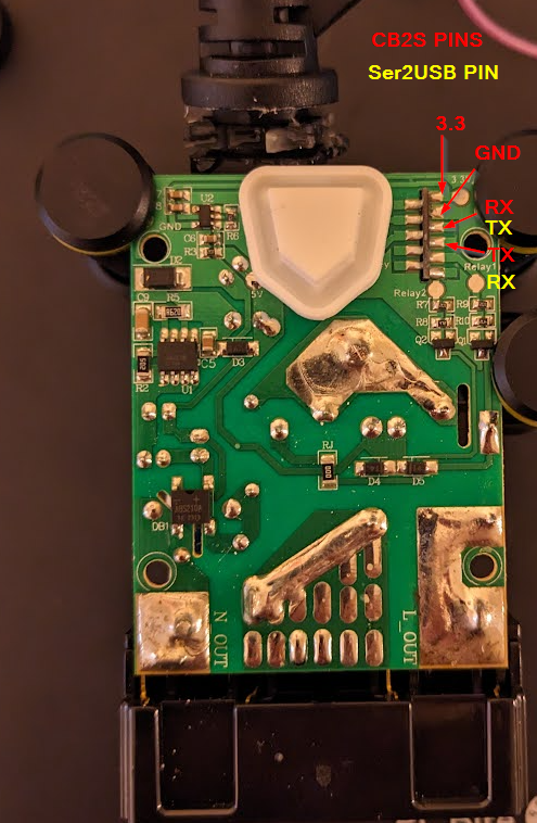
- In the PCB holder and IDing 3.3V, GND, RX, TX pin that need to be connected to the serial to usb device
- Pins connected
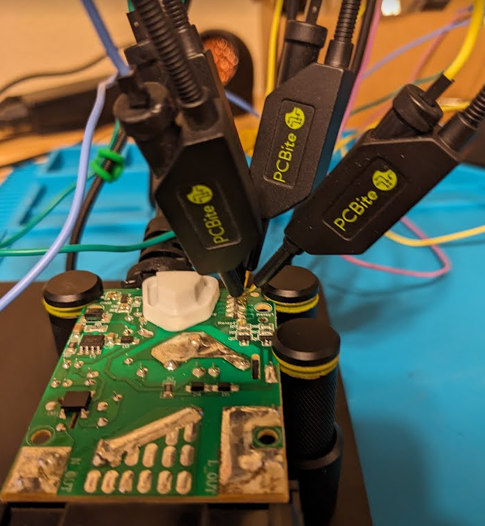
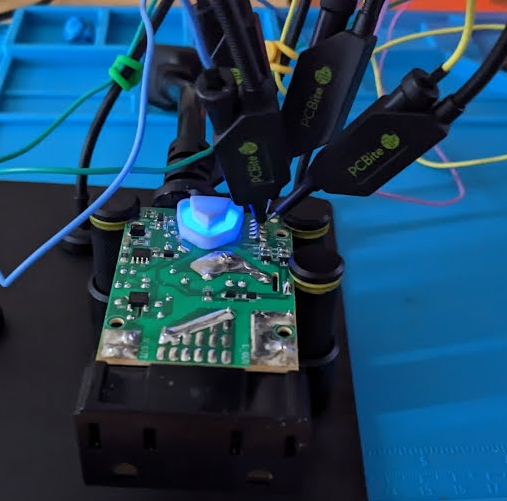
- Powered on and connected to computer
Firmware Dump
- Serial to USB converter connected up to computer and ltchiptool was used to interact with the CB2S module.
- https://github.com/libretiny-eu/ltchiptool
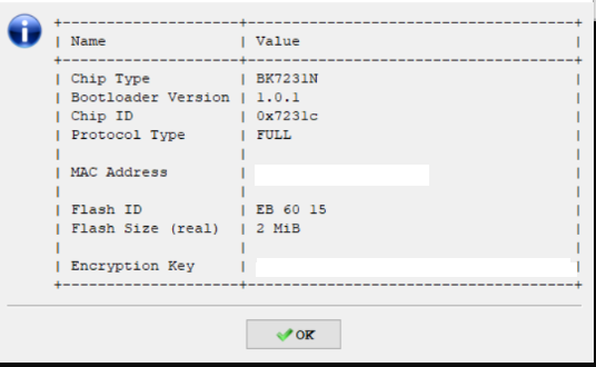
Chip Info
- Chip info showing the BK7231N chip
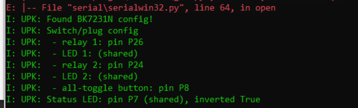
Read Flash
- Firmware saved and re-read in LTChiptool to figure out pin assigments and configurations
ESPHome
ESPHome Config
1
2
3
4
5
6
7
8
9
10
11
12
13
14
15
16
17
18
19
20
21
22
23
24
25
26
27
28
29
30
31
32
33
34
35
36
37
38
39
40
41
42
43
44
45
46
47
48
49
50
51
52
53
54
55
56
esphome:
  name: enbrighten-dual-1
bk72xx:
  board: generic-bk7231n-qfn32-tuya
logger:
web_server:
captive_portal:
mdns:
api:
ota:
wifi:
  ssid: !secret wifi_ssid2
  password: !secret wifi_password2
  fast_connect: true
  manual_ip:
    static_ip: 192.168.X0.XX
    gateway: 192.168.X0.1
    subnet: 255.255.255.0
text_sensor:
  - platform: libretiny
    version:
      name: LibreTiny Version
switch:
  - platform: gpio
    id: switch_1
    name: Relay 1
    pin: P26
    on_turn_on:
      - light.turn_on: light_status
    on_turn_off:
      - light.turn_off: light_status
  - platform: gpio
    id: switch_2
    name: Relay 2
    pin: P24
    on_turn_on:
      - light.turn_on: light_status
    on_turn_off:
      - light.turn_off: light_status
binary_sensor:
  - platform: gpio
    id: binary_switch_all
    pin:
      number: P8
      inverted: true
      mode: INPUT_PULLUP
    on_press:
      then:
        - switch.toggle: switch_1
        - switch.toggle: switch_2
light:
  - platform: status_led
    id: light_status
    pin:
      number: P7
      inverted: true
- In Home Assistant and ESPHome, a new device is created matching the device name in the YAML. Device can be installed, downloaded and flashed using LTChiptool.
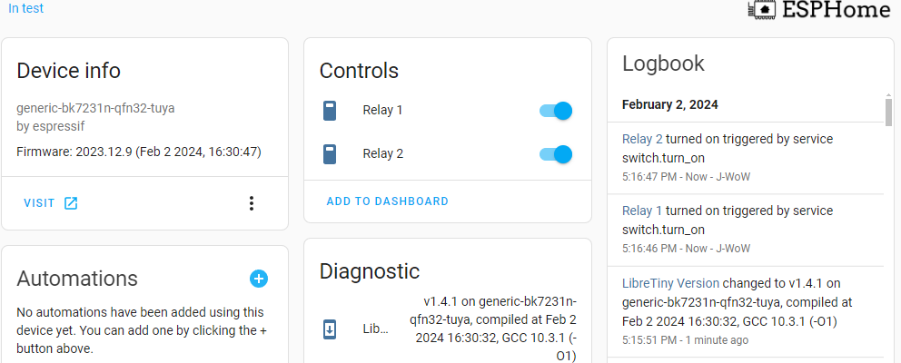
ESPHome Operation
- After flashing and power cycling the device. Pins were unhooked and the 120V outlet is plugged in. After a few seconds the device joined
- ESPHome dashboard showin operation and individual relay operation
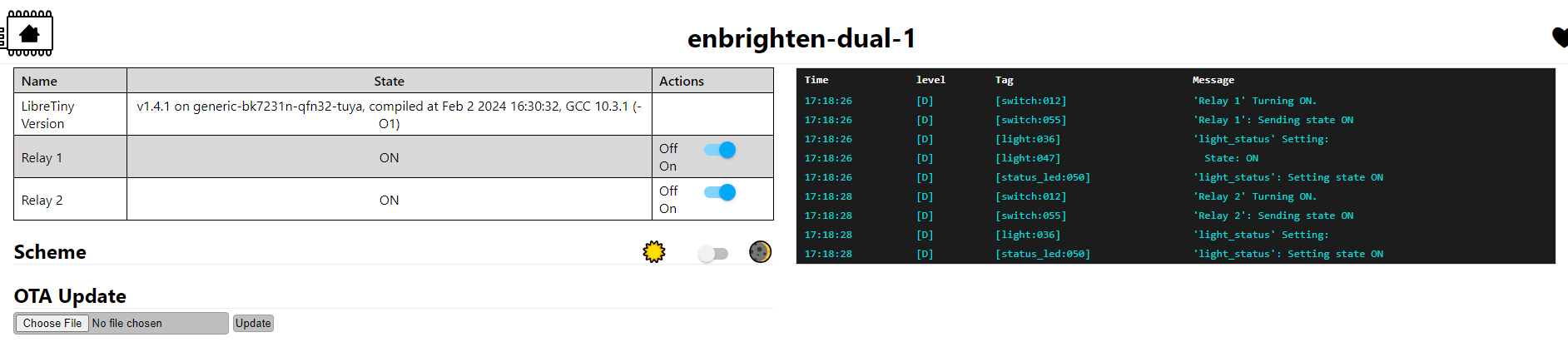
- Webserver view showing the same individual control of the relays for each outlet
Final Thoughts
- The device has two 120v outlets that are controlled independantly. This opens up more fine tuning for automations and control for two different devices. With the BK7321N chip on the CB2S the ESPHome YAML can be updated to also add BLE functionality and turn the outdoor device into a BLE relay.