
- Eight AC outlets with four always on, four smart outlets and four USB-A ports. Looking up information online this looks to have a BK7321X chip so hopefully a good candidate to flash and convert to local control with integrations over ESPHome and Home Assistant.
Device Info
- Model: AHR-083
- FCC ID: 2amxxahr083
Acquisition
- Purchased from Amazon. ~$27.00 + Tax. Four Smart outlets, so roughly $7 per smart outlet. Cheaper than some of the alternative one plug smart outlets.
- Loking up the FCC ID online
- https://fcc.report/FCC-ID/2amxxahr083
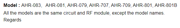
- Model Differences Memo
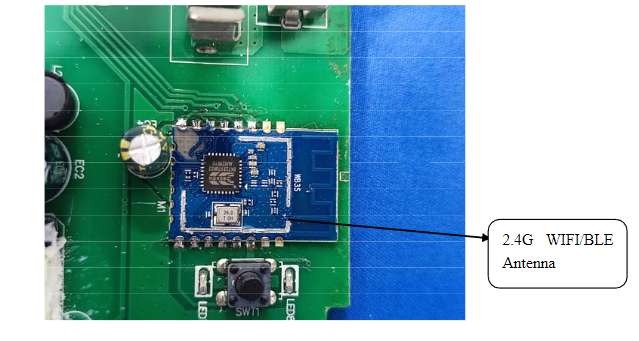
Internal Photos
- Looks like a WB3S Module
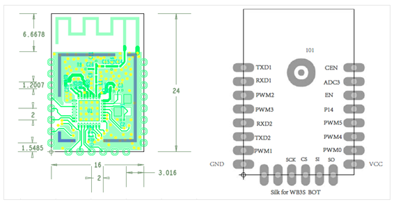
WB3S Module
- Looking up the module
- https://developer.tuya.com/en/docs/iot/wb3s-module-datasheet?id=K9dx20n6hz5n4
Wireless Exploits
- Try to flash the power strip remotely first. If it doesn’t work then will just open up and direct connect to read and write to the chip.
Tuya-Cloudcutter
- https://github.com/tuya-cloudcutter/tuya-cloudcutter
- “This repository contains the toolchain to exploit a wireless vulnerability that can jailbreak some of the latest smart devices built with the bk7231 chipset under various brand names by Tuya. “
- Setup local copy running on a raspberry pi 4b (8GB RAM)
Results
- Worked through the prompts in Tuya-Cloudcutter
![d4527d452b1b0dda590139f7a1693413.png]()
- After some restarts and connections through the prompts…
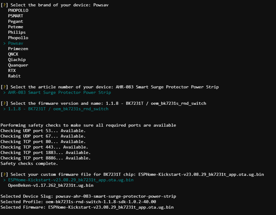

- Did not work » exploit unsuccessful
- Plan B it is… Cracking it open
Teardown & Connections
External Photos
- Top and bottom view of the powerstrip
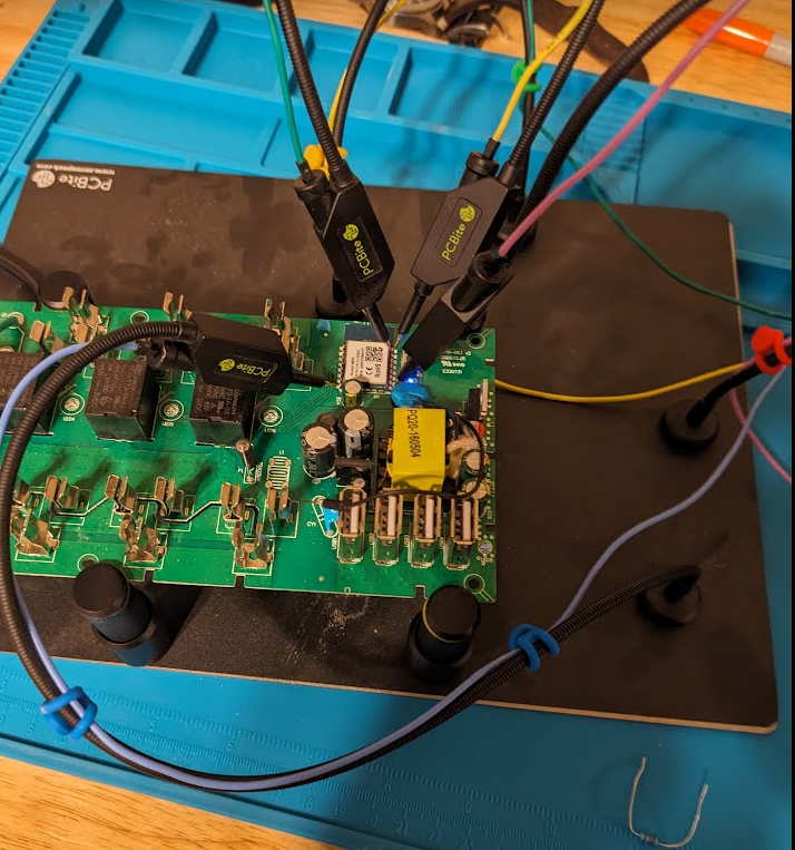
Internal Photos
- Pinout mapping for serial to usb from stock WB3S image online
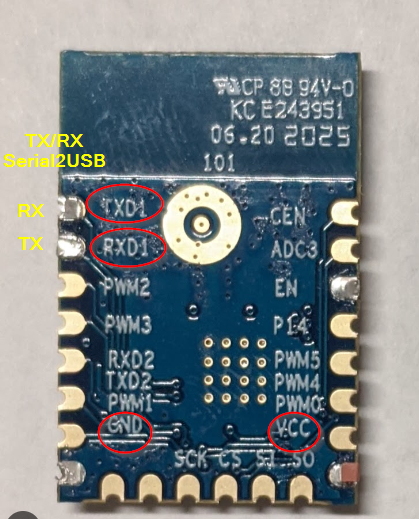
- Connectin the pins
Firmware Dump
- Serial to USB converter connected up to computer and ltchiptool was used to interact with the WB3S module.
- https://github.com/libretiny-eu/ltchiptool
Chip Info
- Reading the chip info
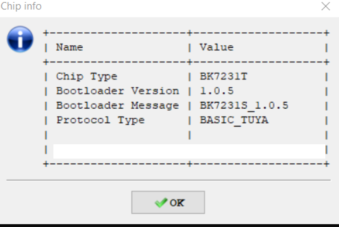
- Looks like the bootloader version is
1.0.5and the Cloud-Cutter version was expecting1.1.8so… maybe that’s why it didn’t work?
Read Flash
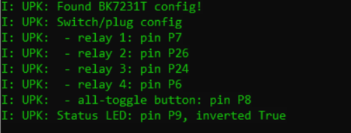
Saving the firmware
Reading firmware back to get pin information and configurations
Write ESPHome-Kickstart
- Instead of setting up a device in ESPHome and downloading the firmware to flash with the direct connection will try out the kickstart flash approach.
- Download the latest kickstart firmware
- https://github.com/libretiny-eu/esphome-kickstart/releases/tag/v23.12.15
- For this device select »
kickstart-bk7231t-2023-12-15.uf2
- Write the
kickstart-bk7231t-2023-12-15.uf2to the chip using LTChiptool - Power cycle the device and the WIFI AP should appear
- Connect to AP and the portal should open in the browser
- Enter Wifi for IOT network and once it joins it pops up in Home Assistant
- Add the device to integrations
ESPHome
ESPHome Config
- With the device added in Home Assistant final touches can be made to clean up config and add static WIFI address.
1
2
3
4
5
6
7
8
9
10
11
12
13
14
15
16
17
18
19
20
21
22
23
24
25
26
27
28
29
30
31
32
33
34
35
36
37
38
39
40
41
42
43
44
45
46
47
48
49
50
51
52
53
54
55
56
57
esphome:
  name: upk2esphome-bk7231t
bk72xx:
  board: generic-bk7231t-qfn32-tuya
logger:
#web_server:
#captive_portal:
mdns:
api:
ota:
wifi:
  ssid: !secret wifi_ssid2
  password: !secret wifi_password2
  fast_connect: true
  manual_ip:
    static_ip: 192.168.X0.XX
    gateway: 192.168.X0.1
    subnet: 255.255.255.0
    dns1: 192.168.X0.1
text_sensor:
  - platform: libretiny
    version:
      name: LibreTiny Version
switch:
  - platform: gpio
    id: switch_1
    name: Relay 1
    pin: P7
  - platform: gpio
    id: switch_2
    name: Relay 2
    pin: P26
  - platform: gpio
    id: switch_3
    name: Relay 3
    pin: P24
  - platform: gpio
    id: switch_4
    name: Relay 4
    pin: P6
binary_sensor:
  - platform: gpio
    id: binary_switch_all
    pin:
      number: P8
      inverted: true
      mode: INPUT_PULLUP
    on_press:
      then:
        - switch.toggle: switch_1
        - switch.toggle: switch_2
        - switch.toggle: switch_3
        - switch.toggle: switch_4
status_led:
  pin:
    number: P9
    inverted: true
- The device can be OTA updated since it is already integrated with Home Assistant
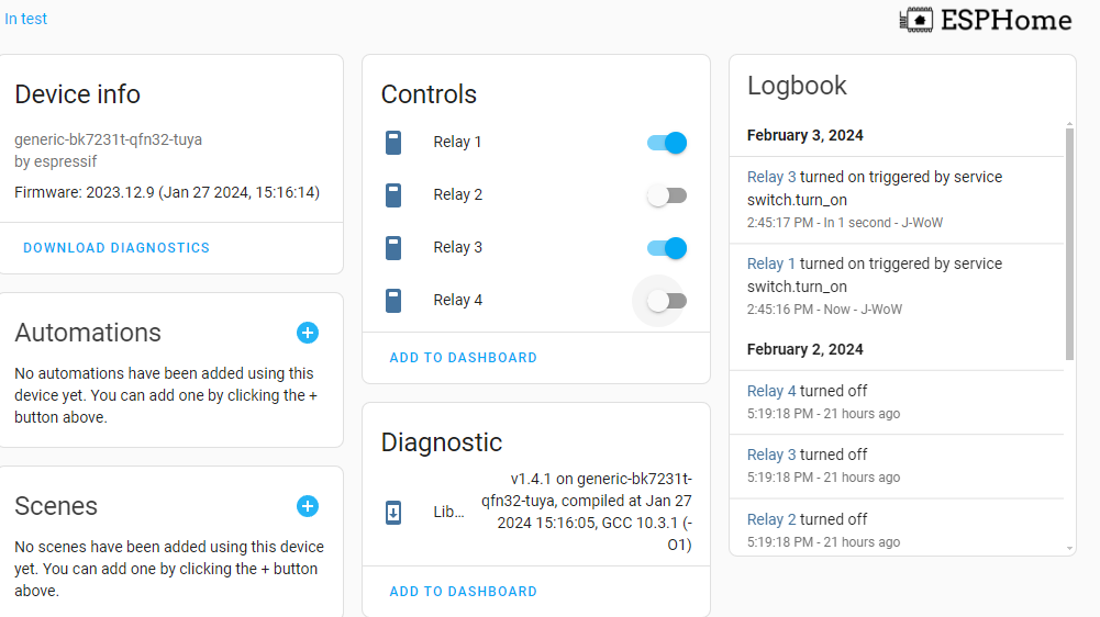
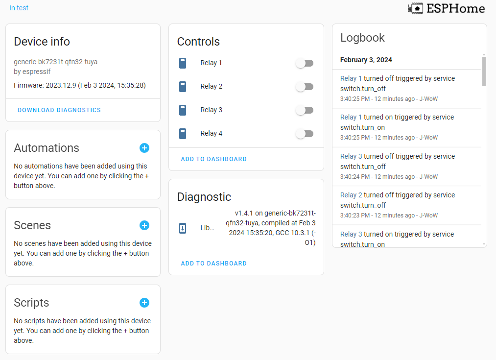
ESPHome Operation
- After OTA check out the device and try out the relay controls in ESPHome Dashboard
Final Thoughts
- Although couldnt get the Tuya-CloudCutter to work the direct flash method using ESPhome-Kickstart was straight forward. With having access to the pin information and the YAML output provided in LTChiptool it might be better to just build the config in ESPHome, download and flash the firmware to reduce the steps and files needed.
- Powerstrip seems solid overall and look forward to having allways on options as well as individual switched outlets all on the same powerstrip.
Second Chance - Tuya-CloudCutter
- Ordered a second one of these from amazon more recently than the first one. There might be a chance that this second one has a more up to date firmware that is compatible with the cloudcutter.
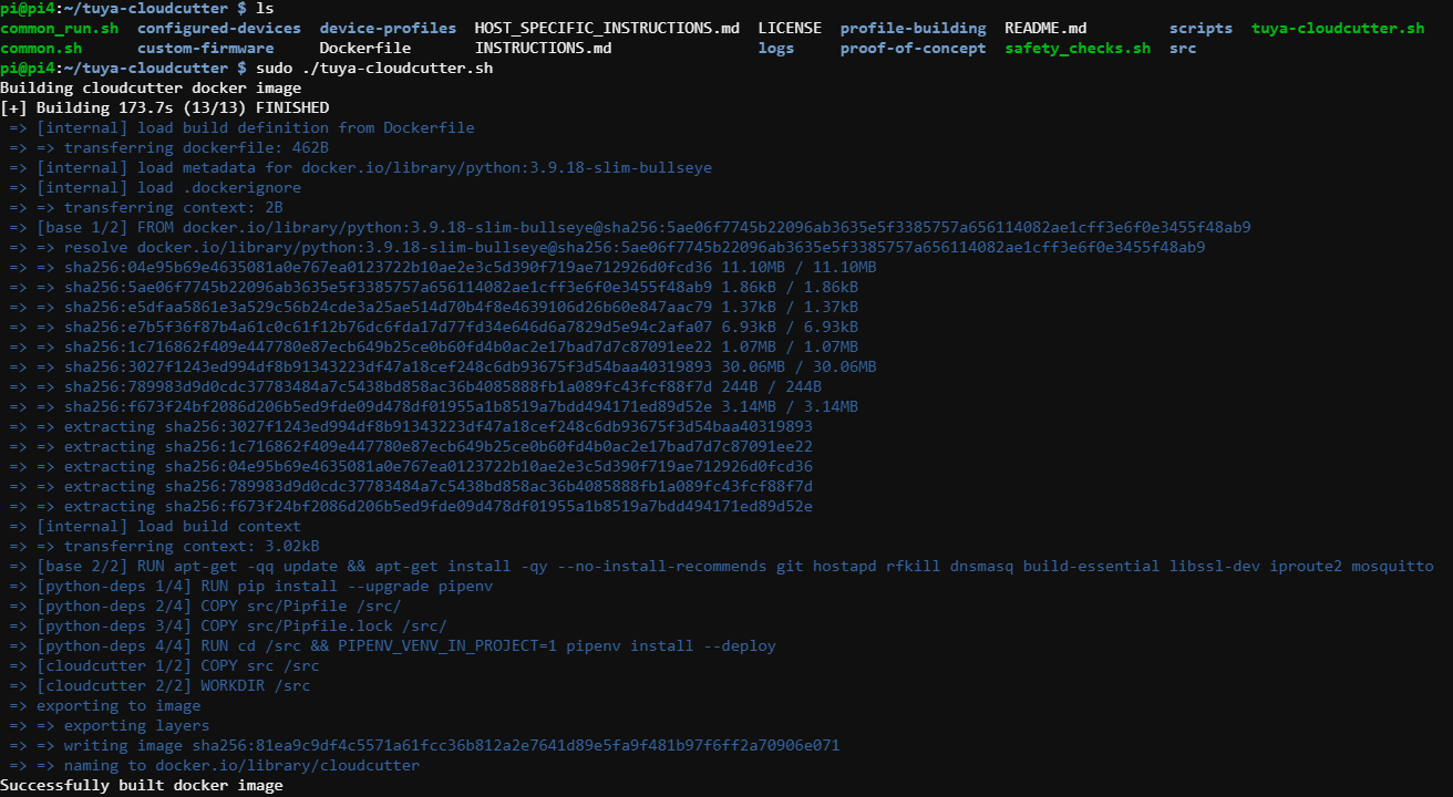
Running CloudCutter
- Fresh build of docker image
- Prompt and selections
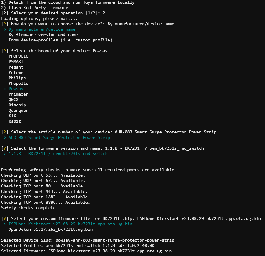
- Put device in slow blink mode and script connects and does it’s magic. One physical power off and on required here.
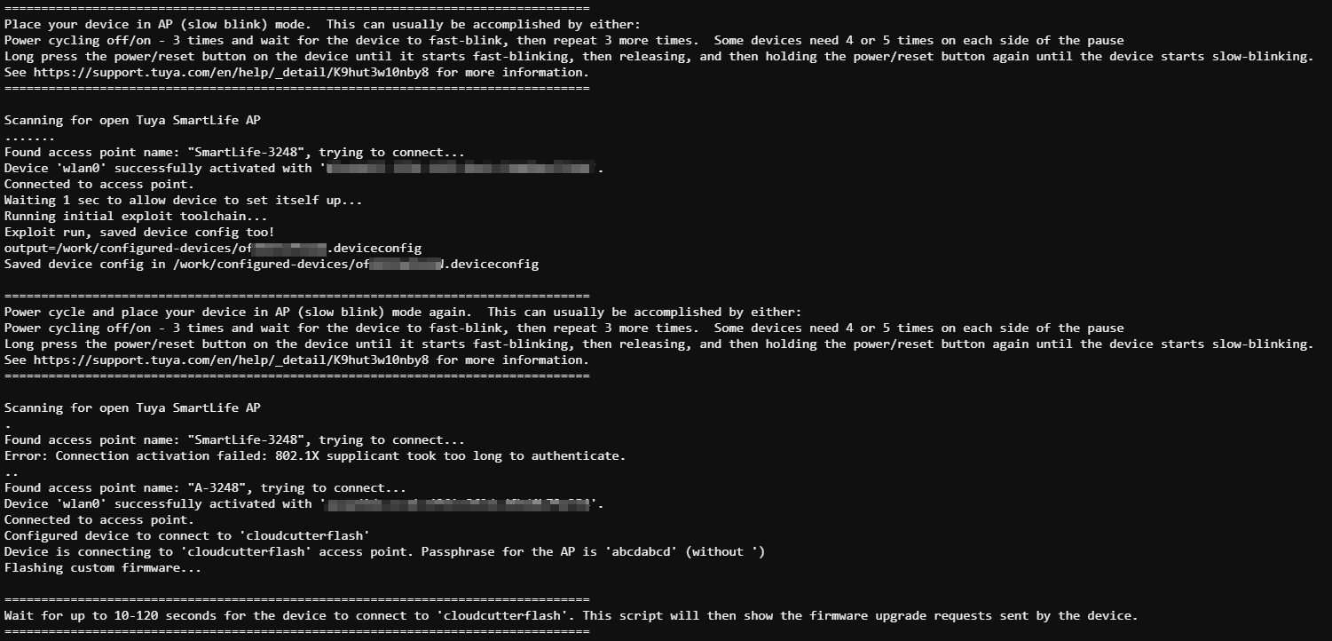
- Made it to the final step! Flashing the ESPHome-Kicktart firmware!
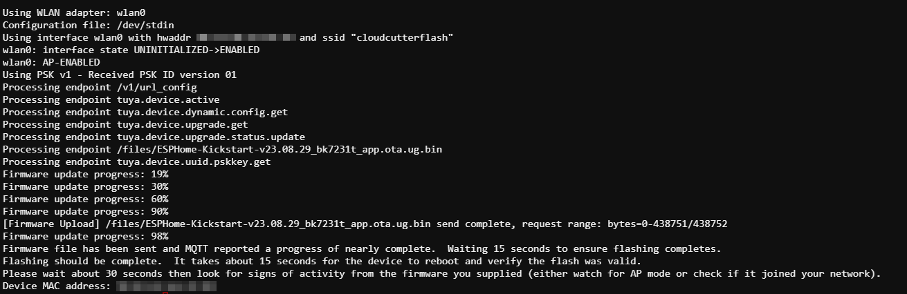
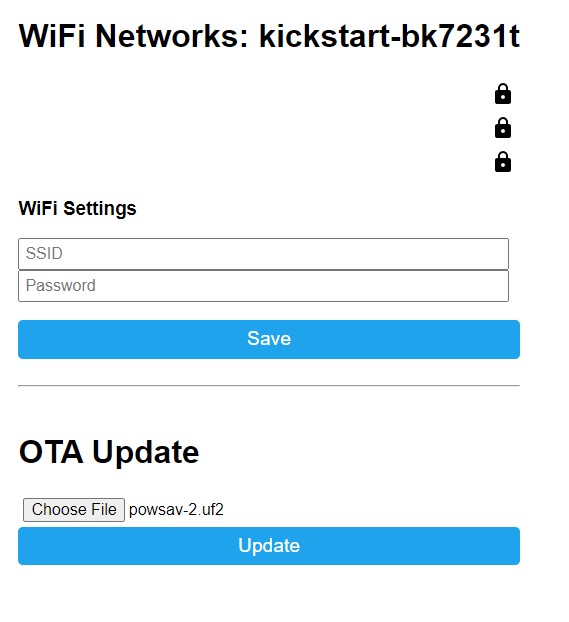
Connecting to new kickstart AP
- Connecting to AP and going to web browser
- In ESPHome, build a new device and copy the YAML settings from the other POWSAV power strip. Rename and change WIFI settings.
- Once OTA upload submitted
new device notificationpops up in Home Assistant - Accepting then integration and trying out the relays in ESPHome
- Looks successful and works as it should. Nice to not have to do a teardown to flash and then put it all back together.